Beam splitters, neutral density filters, technical glass
Precision and quality at a fair price
The stock items listed above can be cut to your desired dimensions and delivered within a few days.
If you are interested in a product, we will provide you with a fair quote. Request your desired product from us now!

Technical glasses
We have a wide range of technical flat glass in sheet formats in standard thicknesses in stock. We can cut these to your desired dimensions within a few days!

Technical glasses
Borofloat 33
Panel dimensions
1150 x 850 mm
Standard thickness
1,1 / 1,75 / 2,0 / 2,75 / 3,30 / 3,8 / 5 / 6,5 mm
Borofloat 33
Panel dimensions
950 x 800 mm
Standard thickness
8,0 mm
B270
Panel dimensions
860 x 840 mm
Standard thickness
1,0 / 1,65 / 2,0 / 2,5 / 3,0 mm
Floatglas
Panel dimensions
1600 x 1200 mm
Standard thickness
2,0 / 3,0 / 4,0 / 6,0 mm
D 263 T eco
Panel dimensions
510 x 430 mm
Standard thickness
0,3 / 0,4 / 0,55 / 0,7 / 1,1 mm
Price
By quantity on request
Achieving reproducible quality
With high-precision measurement technology
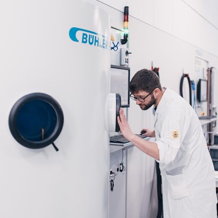
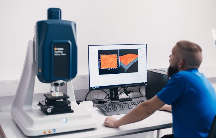
You need reliable high quality in our various precision optics, spherical optics, and technical glass products. We achieve this quality for you thanks to our high-quality measurement technology and measuring equipment.
Upon customer request, we will provide you with a test report containing all the required test characteristics. All materials used are tested in accordance with current specifications and certified upon request. We guarantee you consistently high quality!
- Visual defect inspection
- Angle measurement
- Parallelism measurement
- Interferometer evaluation
- Roughness measurement
- Spectral reflection and transmission measurement
What you can rely on

Made in Germany

International

High quality

Professional

Independent

Personal
Plano optics
Windows and Optical Flats. Customized filters. Precise prisms, wedge plates, and light guides. From specific filter properties to optical or metallic coatings: When it comes to plane optics, we offer the ideal, customized solutions you need for your products and services.
Spherical optics
With MICROS Optics, you are guaranteed lenses, achromats, and cylindrical optics of the highest quality in terms of imaging and beam accuracy. We not only supply the industry with series products, but also deliver prototypes, small series, and pre-series for development and laboratory purposes for cameras and laser technologies.
Technical glasses
Your applications and uses: We develop the optimal solution based on your ideas with refined, technical glass from MICROS Optics. With the latest technologies and consistent process optimization, we can offer you the most economical solution. We supply the entire spectrum of glass refinement as individual parts or large series in consistently tested quality. We take into account what matters: high resistance to acids, alkalis, organic substances, and corrosive environments; high electrical resistance; enormous long-term durability; transmission and reflection; scratch resistance; and mechanical stability—to name just a few.

